Working in Capital for the Xcelerator Digital Thread
The sibling guide to Modeling in Cameo: what arrives from Teamcenter, and how to complete the design in Capital Systems Modeler, Capital Systems Architect, and Capital Logic Designer.
1Onboarding & Overview
1.1 What this guide is, and isn't
This is a completion guide. It tells you what to expect when a design arrives in Capital from Teamcenter, and what you still need to build yourself before it becomes a real electrical design. It is not a Capital training manual, and it stops at the point where the logical connectivity in Capital Logic Designer is complete; physical wire routing and harness manufacturing are handled by further downstream tools outside what this guide covers.
It picks up exactly where the Cameo modeling guide leaves off. That guide covers what to model in Cameo so it survives the trip through Teamcenter. This guide covers the other end: what that data looks like once it lands in Capital, and how to turn it into a complete design.
1.2 The big picture: three tools, one thread
Once a design arrives from Teamcenter, three Capital tools work together, in this order, to turn it into a real electrical design.
Capital Systems Modeler is where functions, signals, and messages live. This is the direct downstream sibling of Cameo's Activities, Ports, and Signals: if you read the Cameo guide, this is where that behavior lands.
Capital Systems Architect is where the platform design takes shape. It takes the functions from Systems Modeler and recognizes them as software or electrical devices that you place in components, decides how the signals between them are routed (over a network, a direct point-to-point electrical connection, or software communication within a shared processor), and lets you run metrics, network bandwidth, memory, CPU load, to check the technical impact of those decisions before committing further.
Capital Logic Designer captures the actual logical connectivity: which devices connect to which, over which nets, built from the platform design Systems Architect established.
Teamcenter  ▶▶  Systems Modeler  ▶▶  Systems Architect  ▶▶  Logic Designer
(functions,       (functions, ports,      (platform design:       (logical
 signals)          signals, messages)      allocation, signal       connectivity:
                                            routing, metrics)        devices + nets)
A function or signal that isn't complete when it arrives doesn't quietly fail somewhere downstream; it fails a design rule check, in the tool where the gap actually is. Section 3 covers exactly what to check, and where.
Those three tools are the first four steps of a much longer Electrical Digital Lifecycle Process. This guide covers steps 1 through 4, Functional Design through Electrical Schematic; everything from Electrical Wire Diagrams onward is further downstream and outside this guide's scope.
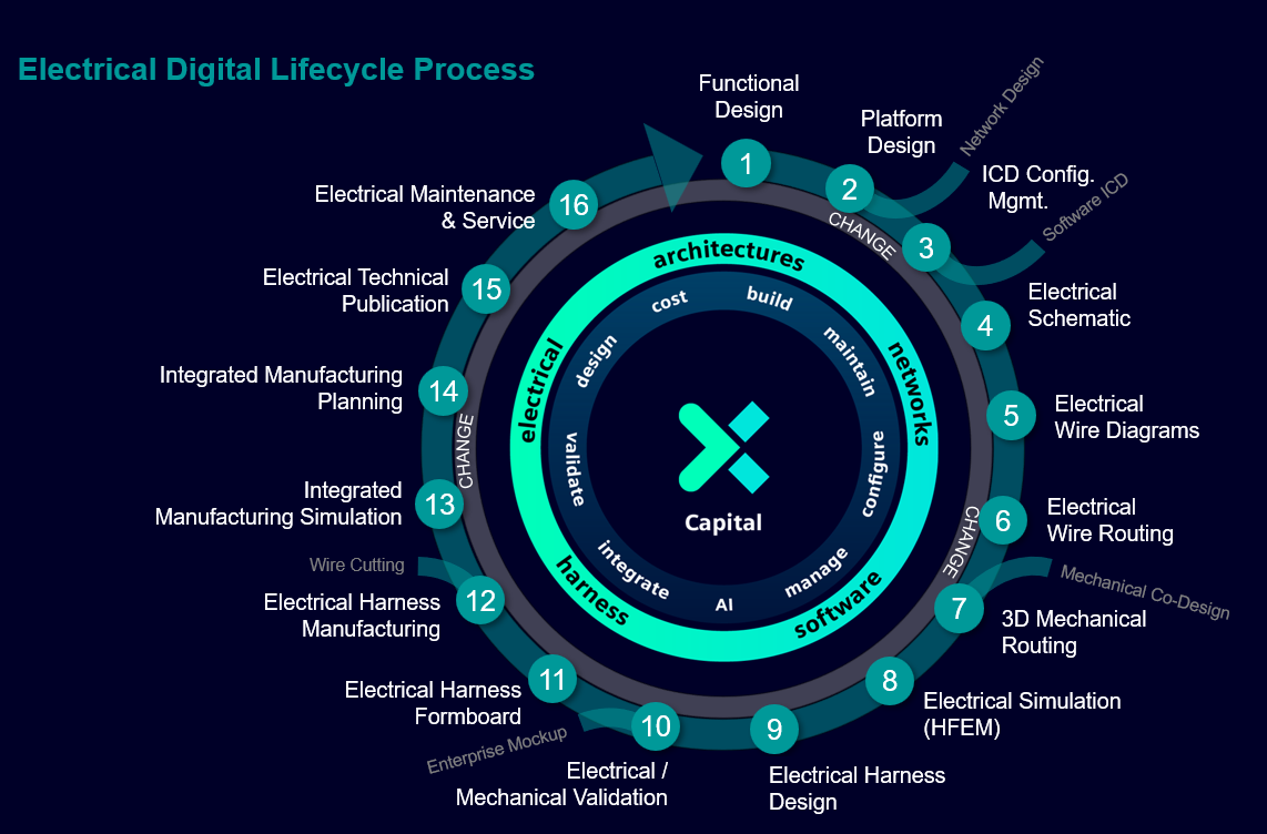
1.3 A few words you'll see everywhere
Full definitions live in the Glossary, but here are the load-bearing ones up front.
- Function: something the system does, arriving from a Cameo Activity by way of Teamcenter. Lives in Capital Systems Modeler.
- Signal / Message: data conveyed between functions. Must match an entry in the Capital Dictionary to be considered complete.
- Allocation: assigning a Function to the device that performs it, decided in Capital Systems Architect.
- Device: a software or electrical component, recognized from a Function and placed in the platform design in Capital Systems Architect.
- Net: a logical connection between devices in Capital Logic Designer, before any physical wire exists.
1.4 Where this fits in the bigger picture
The full thread runs: a systems engineer models in Cameo, the HCL Cameo-Teamcenter connector lands that model in Teamcenter, and from there it becomes available to Capital. This guide starts at that arrival point. If you need the modeling-side detail, the Cameo guide covers it in full; you don't need to read it to use this one, but the terminology in Section 3.2 will make more sense if you have.
1.5 Who does what
| Role | Responsible for |
|---|---|
| Function / Signal Modeler | Completing function, signal, and message definitions in Capital Systems Modeler, and keeping them consistent with the Capital Dictionary |
| Platform Architect | Allocating functions to devices and deciding signal routing in Capital Systems Architect, and reviewing the resulting metrics |
| Logic / Schematic Designer | Building and maintaining the logical connectivity (devices and nets) in Capital Logic Designer |
| PLM Administrator | The Teamcenter side of the bridge: what crosses, and in which direction (see the Cameo guide's Section 5) |
1.6 Quick starts by role
A condensed "day one" for each role, pointing at the sections that matter most so you don't have to read the whole guide before doing anything.
Function / Signal Modeler
Before you start: confirm your Capital Dictionary is up to date with the network signals and messages your program uses. A function or signal that doesn't match the dictionary fails a design rule check on arrival.
- Read 3.2 to see exactly what arrives as a Function versus what you still need to complete.
- Run the 3.5 checklist before handing a design to the next role.
Platform Architect
Before you start: a Function that isn't allocated to a device has nowhere for Logic Designer to build connectivity from. This is the single most common blocker for a design that otherwise looks complete.
Logic / Schematic Designer
Before you start: confirm every function you expect to see has already been allocated to a device in Systems Architect (see 3.3); Logic Designer builds its schematic from that platform design, not from Systems Modeler directly.
- Read 3.3 for how the three tools relate.
- Read the Worked Example once before working a real design.
2Value: Why Completing the Work in Capital Matters
2.1 The problem today, stated plainly
Two specific gaps show up when a design arrives from Teamcenter incomplete.
First: a function or signal can arrive without a matching dictionary entry. Capital Systems Modeler checks that the dictionary signal name and revision on a functional signal or message actually match a real network signal or message; if they don't, the design rule check flags it, but only if someone runs the check. Left unnoticed, the signal exists in the model without being real anywhere else.
Second: a function can arrive allocated to nothing. A Function and its Signal can be completely correct in Systems Modeler, and still have no device behind them, because nobody has allocated the function to anything in Capital Systems Architect yet. That gap is invisible until someone tries to build the Logic Designer schematic and finds the function missing.
2.2 What completing the work correctly buys you
Design rule checks catch the gap where it actually is. Capital Systems Modeler, Capital Systems Architect, and Capital Logic Designer each run their own design rule checks, appearance, connectivity, consistency, naming, and dictionary matching among them. A gap caught here is a message in an output window, with a link to the exact object; a gap missed here is a schematic that doesn't match the design intent.
Architecture decisions get tested before they're expensive to change. Capital Systems Architect lets you iterate quickly on allocation and signal-routing decisions and see the downstream technical impact, network bandwidth, memory, CPU load, before committing further, rather than discovering a bad architecture decision after a schematic already exists around it.
Traceability continues instead of stopping at the import. A Function and Signal that arrive correctly from Teamcenter stay linked all the way through the platform design and into the logical connectivity that finally carries them, which is the point of the whole thread, not just the modeling half of it.
2.3 Honest caveats
This guide covers the receiving end of a bridge that is real and working, but not finished. As of this writing:
- Capital Systems Modeler also supports importing SysML projects directly (for example, from IBM Engineering Systems Design Rhapsody). Whether that path and the Teamcenter-mediated path described here produce equivalent results is not covered by this guide.
- The exact field-level mapping between a Teamcenter attribute and a Capital Dictionary entry depends on your program's mapping-file configuration; see your PLM administrator.
- This guide deliberately stops at Capital Logic Designer's logical connectivity. Physical wire routing and harness manufacturing are handled by further downstream tools not covered here.
3Working in Capital: What Arrives, and What You Complete
3.1 The one idea to hold onto
A design rule check only catches what it's asked to catch, and only when someone runs it. The three tools cover different halves of the design: Systems Modeler covers function and signal definition; Systems Architect covers allocation and signal routing; Logic Designer covers the resulting logical connectivity. A design that looks complete in one tool can still be missing something the next tool needs. Section 3.2 tells you exactly what to check, and where.
3.2 What arrives from Teamcenter, and where it lands
| What arrives | What it means | Where it lands, and what you complete |
|---|---|---|
| Function | A function the system performs (from a Cameo Activity) | A Function object in Capital Systems Modeler. Add it to a diagram, and give it Ports if they didn't arrive typed. |
| Signal / Message | Data conveyed between functions | A functional Signal or Message in Capital Systems Modeler. Its Dictionary Signal Name and Revision must match a real entry in the Capital Dictionary, or a design rule check flags it. |
| Component (logical) | A part of the system that performs a function | Recognized as a Device in Capital Systems Architect once the Function is allocated to it. It has no logical connectivity yet. |
| Port / typed connection point | An interface point on a function or component | A Port on the Function (Systems Modeler), carried through to the Device once it's recognized (Systems Architect). |
| The allocation (function to component) | Which part performs which function | Carried as data from Teamcenter, but not acted on until you recognize the device and confirm the allocation in Capital Systems Architect; see 3.6. |
| Not carried automatically | Signal routing decisions (network, electrical, or software), and anything downstream of logical connectivity | Decided directly in Capital Systems Architect; see 3.6. |
3.3 How the three tools relate
Capital Systems Architect takes the functions and components from Capital Systems Modeler and turns them into a platform design: functions are recognized as software or electrical devices, placed in components, and their signals are routed as network, electrical, or software connections. This happens alongside running metrics, bandwidth, memory, CPU load, to check the technical impact of those decisions before treating the architecture as final.
Capital Logic Designer then captures the actual logical connectivity based on that platform design: a system design, where connections are represented as Nets. A system design can be converted into a wiring design, where devices and connectors are connected with Wires, directly inside Capital Logic Designer itself.
This guide's scope ends at that point. Physical wire routing and harness manufacturing are handled by further downstream tools outside what this guide covers.
3.4 The decision point: how to route each signal
A signal between two functions doesn't route itself; Capital Systems Architect requires a deliberate decision for each one.
Network routes the signal over a shared bus (for example CAN or Ethernet), sharing bandwidth with other signals on the same network. Check the bandwidth metrics before committing a signal to a busy network.
Point-to-point electrical routes the signal as a direct connection between two devices; simplest to reason about, but doesn't scale to a signal with many listeners.
Software routes the signal within a shared processor, with no physical connection at all; only valid when both functions are allocated to the same device.
Whichever you choose, the decision belongs in Capital Systems Architect, before Capital Logic Designer builds the logical connectivity from it.
3.5 A completion checklist
Before you hand a design to the next role, check it against this list.
- Every Function that needs one has its Ports added, typed to match what it connects to.
- Every Signal and Message's Dictionary Signal Name and Revision match a real entry in the Capital Dictionary; a mismatch here is a design rule check finding, not a guess.
- Every Function that needs to be part of the platform design is allocated to a device in Capital Systems Architect. A Function without one has nothing for Logic Designer to build connectivity from.
- Every signal's routing (network, electrical, or software) has been decided deliberately, not left to whichever happens by default.
- Metrics (bandwidth, memory, CPU load) have been reviewed before treating the architecture as final.
- Design rule checks have been run in every tool the design has touched, not just the last one.
3.6 What never arrives automatically, and why that's fine
Some things are genuinely outside what a functional model can carry, by design, not by omission.
- Allocation (which device performs which function) is an architecture decision, not a functional one; nothing in a Function definition implies which device should perform it.
- Signal routing (network vs. electrical vs. software) reflects platform-level tradeoffs, bandwidth, cost, complexity, that have no equivalent in a functional design.
- Physical wire routing and harness manufacturing detail live in further downstream tools, beyond this guide's scope.
3.7 Before and after: a gallery of common mistakes
| Common mistake | Why it breaks | The fix |
|---|---|---|
| A functional signal's dictionary name or revision doesn't match a real network signal | A design rule check flags it, but only once someone runs the check; until then the signal looks complete but isn't real anywhere else | Keep the Capital Dictionary current, and run the Systems Modeler design rule checks before handing off (3.5) |
| A function is left unallocated to any device in Systems Architect | Logic Designer has nothing to build connectivity from for that function; the schematic is missing devices that look present in Systems Modeler | Allocate every function to a device before building the Logic Designer schematic (3.5) |
| Two equivalent signals are routed inconsistently (one as network, one as point-to-point electrical) with no stated reason | Produces an architecture with no clear rationale, which is expensive to untangle later | Decide each signal's routing deliberately, and document why (3.4) |
| Metrics aren't reviewed before the architecture is treated as final | A bandwidth or memory problem is discovered only after the Logic Designer schematic (or something later) is built around it, when it's expensive to change | Review metrics in Systems Architect before treating an allocation as final (3.4) |
4Worked Example: The Gimbal, Continued Into Capital
This continues the Camera and Image Processor thread from the Cameo guide's Worked Example. There, a function called Process Image was modeled with two components, Camera and Image Processor, connected by a Signal carrying Raw Image. Here is what that looks like once it arrives in Capital, and what completes it.
Part A: What arrives in Capital Systems Modeler
- The Process Image Function arrives, with Ports.
- The Raw Image Signal arrives as a functional signal on the Function. Its Dictionary Signal Name may or may not already match a real network signal; check this first (3.5).
- Camera and Image Processor arrive as the components the Cameo guide allocated Process Image to. Capital Systems Modeler carries that allocation as data, but nothing downstream recognizes them as devices yet.
Part B: Complete the platform design in Capital Systems Architect
- Open Process Image in Systems Architect. Recognize Camera and Image Processor as electrical devices, and place them in components.
- Decide how Raw Image is routed between them: a direct point-to-point electrical connection, since this is a two-device link with no other listeners (3.4).
- Review the metrics (bandwidth, memory, CPU load) before treating this allocation as final.
Part C: Build the logical connectivity in Capital Logic Designer
- Confirm a Net connects Camera's output port to Image Processor's input port, carrying Raw Image, reflecting the routing decision made in Systems Architect. If it isn't there yet, build it directly: this is a system design at this point, not yet a wiring design.
- Run the Logic Designer design rule checks. A dictionary mismatch on Raw Image shows up here, before it becomes harder to trace.
- If your program converts this system design into a wiring design directly inside Logic Designer, do so now, and run final design rule checks.
Mistakes made (and fixed) in this walkthrough
| What went wrong | What fixed it |
|---|---|
| Assumed the Raw Image dictionary entry already existed | Checked the Capital Dictionary directly rather than assuming; it needed to be added |
| Tried to build the Logic Designer net before Camera and Image Processor were recognized as devices in Systems Architect | Logic Designer had nothing to connect; allocated both devices first, then re-tried |
| Routed Raw Image as a network signal by default, without checking whether a direct connection made more sense | Reviewed the routing decision deliberately, and switched to point-to-point electrical |
Try it yourself
Using the Cameo guide's Battery Monitor practice exercise (Battery, Charge Controller, Display, function Report Charge Level): once that function and its signal arrive in Capital, complete the same three parts here: allocate all three components in Systems Architect, decide how the charge-level signal is routed, and build the net-level schematic in Logic Designer.
Check your work
- Does the charge-level signal's dictionary name match a real network signal, not just a name you assumed was already there?
- Are all three components recognized as devices in Systems Architect before you try to build the Logic Designer schematic?
- Did you decide the signal's routing deliberately (network, electrical, or software), rather than leaving it to a default?
- Does the Logic Designer net actually connect the right ports, not just imply the right components are present?
5How the Data Flows Through Capital
5.1 What each tool owns
- Capital Systems Modeler owns functional definition: functions, ports, signals, messages.
- Capital Systems Architect owns the platform design: allocation of functions to devices, signal routing decisions, and the bandwidth, memory, and CPU metrics that validate them.
- Capital Logic Designer owns logical connectivity: devices and nets, built from the platform design.
5.2 What crosses automatically, what needs configuration, and what never crosses
| Category | Examples |
|---|---|
| Crosses automatically | Functions, Ports, Signals and Messages, the Cameo-side allocation of a function to its component (as data, not yet acted on) |
| Crosses, but only with configuration | The mapping between a Teamcenter attribute and a Capital Dictionary entry; owned by your PLM administrator's mapping file |
| Never crosses, by design | Which device-recognition and signal-routing decisions to actually make in Systems Architect; physical wire routing and harness manufacturing (further downstream, out of scope) |
| Needs a deliberate decision, not a default | How each signal is routed: network, point-to-point electrical, or software |
5.3 The round trip
Enrichment made in Capital, part numbers, physical attributes, platform design detail, can flow back to Teamcenter rather than staying siloed in Capital. Whether that happens automatically for your program, and which fields are Capital-authoritative versus Teamcenter-authoritative, is a configuration decision owned by your PLM administrator, the same ownership split the Cameo guide describes for the outbound direction.
5.4 When something you expect from Cameo isn't in Capital
The object existing in Teamcenter is not the same thing as the object being in the structure Capital reads. This was found directly: a Teamcenter item held over a hundred objects that had all landed correctly, individually readable and correct, but zero of them were attached to any product structure. Every downstream reader, Capital included, saw an empty design, because the tools that pull from Teamcenter read structure, not a flat inventory of objects that happen to exist. If a component, function, or signal is missing from what arrives in Capital, that's the first thing to have your PLM administrator check, ahead of assuming the Cameo model itself is wrong.
Two things on the Cameo side commonly cause a real gap rather than a structure problem, worth knowing so you can describe the symptom precisely when you ask:
- A port with nothing landed. On the Cameo side, a port only becomes real in Teamcenter once it's owned by a block that itself has a parent with composite part properties. A port on an orphaned or unparented block simply never lands, with no error shown to the modeler.
- A connector or signal path with nothing landed. Both need to have been wired correctly at the moment they were created in Cameo; editing an existing connector's endpoints or an item flow's source/target afterward is silently ignored on the Cameo side. See the Cameo guide's Section 3.4b.
And one Teamcenter-side interlock worth knowing: an Allocate modeled backwards in Cameo (Activity as client instead of Block) doesn't just fail to cross, it aborts that Check-In entirely and blocks every later one for that model. If a design that used to update stops updating from Cameo altogether, ask whether an allocation was recently added or edited before looking anywhere else.
5.4 The honest state of automation today
The function, signal, and component data described in this guide is proven to cross correctly at real scale. What still requires a deliberate configuration decision, per the open items in Section 2.3, is the exact field-level mapping for Dictionary entries, and whether the direct SysML import path available in Capital Systems Modeler is meant to replace or supplement the Teamcenter-mediated path this guide describes.
6Appendix
6.1 Glossary
- Function
- Something the system does. Lives in Capital Systems Modeler, arriving from a Cameo Activity by way of Teamcenter.
- Signal / Message
- Data conveyed between functions. Must match a real entry in the Capital Dictionary to be considered complete.
- Capital Dictionary
- The reference source of real network signals and messages that functional signals and messages are checked against.
- Allocation
- Assigning a Function to the device that performs it, decided in Capital Systems Architect.
- Device
- A software or electrical component, recognized from a Function and placed in the platform design in Capital Systems Architect.
- Signal Routing
- The decision of how a signal moves between devices, network, point-to-point electrical, or software, made in Capital Systems Architect.
- Metrics
- Measurements, network bandwidth, memory (RAM, ROM, Flash), CPU load, that Capital Systems Architect can run against a platform design to check the technical impact of allocation and routing decisions.
- Net
- A logical connection between devices, before any physical wire exists. The connections in a system design.
- Wire
- A physical conductor connecting devices and connectors, in a wiring design.
- System Design
- A Capital Logic Designer design where connections are represented as Nets.
- Wiring Design
- A Capital Logic Designer design where devices and connectors are connected with Wires.
- Capital Systems Modeler
- The Capital tool for functional definition: functions, ports, signals, and messages.
- Capital Systems Architect
- The Capital tool for platform design: recognizing functions as devices, allocating them to components, routing the signals between them, and running metrics against the result.
- Capital Logic Designer
- The Capital tool for logical connectivity: devices and nets, built from the platform design.
- Design Rule Check (DRC)
- An automated check for a specific category of problem (appearance, connectivity, consistency, naming, dictionary matching); must be run to catch what it checks for.
6.2 Frequently Asked Questions
What's the difference between Capital Systems Modeler and Capital Systems Architect?
Systems Modeler defines what a system does, functions, ports, and signals, independent of implementation. Systems Architect takes those functions and decides how they're actually realized: which device performs which function, and how the signals between them are routed.
Why did my function's signal fail a design rule check even though the model looked right in Cameo?
Most likely a dictionary mismatch: the signal's Dictionary Signal Name or Revision doesn't match a real entry in the Capital Dictionary yet. This is a Capital-side completion step, not something Cameo modeling alone can guarantee.
My Logic Designer schematic is missing a device I expect to see.
Most likely that function hasn't been allocated to a device in Capital Systems Architect yet. Logic Designer builds its connectivity from the platform design; a function with no allocation has nothing for it to connect.
Do I have to convert a system design into a wiring design?
Not always. Many programs keep a design as a system design (Nets) through this guide's scope, and only convert it when a later step in their process requires Wires. If your program does convert, it happens directly inside Capital Logic Designer.
6.3 Where to Get Help
Names below are placeholders; each row needs a real owner filled in.
| Question about | Ask |
|---|---|
| Whether a function or signal arrived correctly from Teamcenter | [PLM administrator, TBD] |
| Capital Dictionary entries and mapping-file configuration | [PLM administrator, TBD] |
| Platform design, allocation, and signal-routing questions | [Systems Architect lead, TBD] |
| Logical design and connectivity questions | [Logic Designer lead, TBD] |
| A modeling question this guide didn't answer | Use Suggest an edit at the top of this page; it goes straight into the review queue |
6.4 Changelog
| Date | Change |
|---|---|
| 2026-07-23 | First full draft published, grounded in the Capital Systems Modeler, Capital Logic Designer, and Capital Systems Integrator documentation, continuing the Cameo guide's Gimbal worked example into Capital. |
| 2026-07-23 | Corrected the guide's tool pipeline: Capital Systems Architect, not Capital Systems Integrator, is the platform-design tool between Systems Modeler and Logic Designer. Removed all Capital Systems Integrator content (slots, harness topology, wiring synthesis), which is out of this guide's scope, and rebuilt the completion checklist, mistakes gallery, and Worked Example around allocation, signal routing, and metrics in Systems Architect. |
| 2026-08-21 | Added Section 5.4, "When something you expect from Cameo isn't in Capital," from 21 real Check-Ins driven headlessly against a live Teamcenter: the object-exists-but-isn't-in-structure gap, the two common Cameo-side reasons a port or connector never lands, and the Allocate-direction interlock that blocks all later Check-Ins for a model. |